Split Case Double Suction Pump Impeller Optimization: A Collaborative Design Strategy for Reducing NPSHr & Energy Consumption
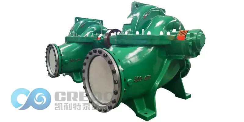
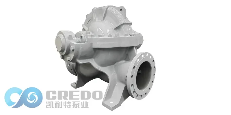
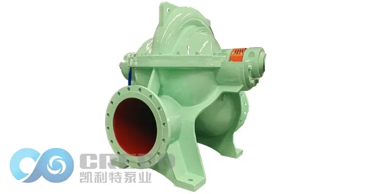
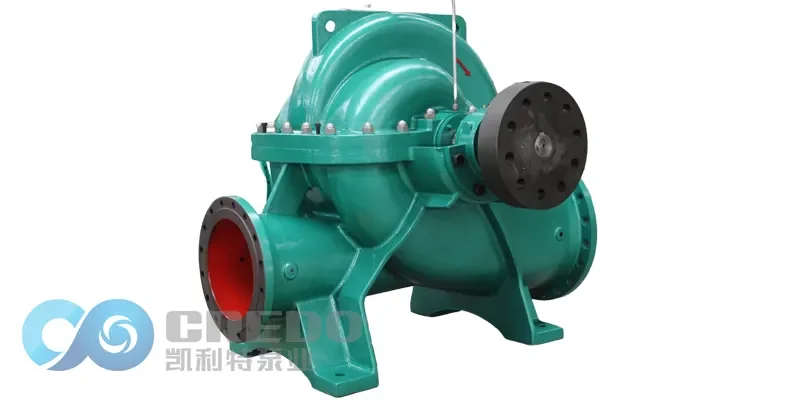
Split case double suction pumps (horizontal split-case centrifugal pumps) are widely used in high-flow scenarios such as municipal water supply and power plant circulation systems due to their symmetrical structure and ease of maintenance. However, the impellers are prone to cavitation caused by localized low-pressure zones during high-speed operation, leading to efficiency drops and excessive vibration. This article proposes a comprehensive solution to reduce NPSHr (Net Positive Suction Head Required) and optimize energy efficiency through three dimensions: impeller geometric redesign, flow channel matching, and system-level coordination.
1. Cavitation Characteristics and Design Challenges in Split Case Double Suction Pumps
While double suction impellers offer flow symmetry advantages, they exhibit two typical cavitation risk zones:
Low-pressure zone at the blade leading edge: Sudden velocity gradient changes at the mid-tongue of the impeller create localized pressure below the vaporization threshold.
Volute tongue interaction zone: Periodic pressure pulsations caused by clearance flow (3%–5% of impeller diameter) between the impeller outlet and volute tongue.
Experimental data indicate that when flow deviates by ±15% from the Best Efficiency Point (BEP), the NPSHr of split case pumps can surge by 40%. Traditional designs often sacrifice efficiency to achieve low NPSHr. Thus, multi-parameter collaborative optimization is essential for performance breakthroughs.
2. Key Geometric Optimization Technologies for Double Suction Impellers
2.1 Asymmetric Blade Wrap Angle Design
Differentiated leading-edge wrap angles: Assign unequal wrap angles to the impeller’s suction and discharge sides (e.g., β₁=28° at the inlet side, β₂=32° at the outlet side) to mitigate velocity sudden change at the mid-tongue. CFD simulations show this design reduces pressure standard deviation in impeller channels by 22%.
3D twisted blades: Use parametric modeling tools (e.g., ANSYS BladeGen) to generate axially tapered blade profiles, reducing the installation angle at the blade tip by 5°–8° compared to the hub. This eliminates secondary flows. A municipal water plant retrofit case demonstrated NPSHr reduction from 6.3m to 4.1m.
2.2 Impeller-Volute Dynamic Matching
Variable-section volute: Install adjustable diffuser vanes at the volute outlet to automatically modulate the diffusion angle (8°–15°) based on real-time flow rates. At 70% BEP, reducing the vane angle to 10° maintains safe flow velocities (4–6 m/s) in the volute.
Stepped volute tongue: Replace the traditional right-angle tongue with a three-step structure (height difference Δh=0.03D₂ per step) to reduce backflow impact. Tests show this design lowers cavitation-induced vibration velocity from 7.1 mm/s to 3.8 mm/s in a 200mm-diameter pump.
3. Low-NPSHr Materials and Surface Treatment Technologies
3.1 Composite Impeller Manufacturing
Stainless steel-ceramic hybrid blades: Bond 2mm-thick silicon nitride (Si₃N₄) ceramic layers to 06Cr13Ni4Mo stainless steel substrates via explosive welding. The ceramic layer (hardness 1500 HV) extends cavitation resistance lifetime to 3.2× that of conventional impellers.
Laser-clad nickel-based alloy: Apply a 0.5mm-thick Inconel 625 coating on blade pressure surfaces. The high-entropy alloy effect suppresses microcrack propagation. A seawater pump test showed stable operation for 8,000 hours under 5% gas content.
3.2 Superhydrophobic Surface Modification
Spray graphene-PTFE composite coatings (contact angle >150°) on impeller channel walls. Hydrophobic effects reduce flow resistance, improving efficiency by 2.1% in a 2,000m³/h pump while lowering the critical NPSHr for incipient cavitation by 0.4m.
4.System-Level Optimization and Intelligent Control
4.1 Dual-Inlet Pressure Stabilization
Install symmetrically arranged bellmouths at the pump inlet, designed with an Archimedean spiral profile (r=θ/2π) to induce pre-swirl. Combined with guide ribs (height = 1/8 pipe diameter), this reduces inlet velocity non-uniformity from 12% to <5%.
4.2 Cavitation Warning and Adaptive Compensation
Acoustic emission monitoring: Deploy broadband sensors (20kHz–1MHz) on bearing housings. Wavelet packet decomposition extracts cavitation signatures (120–180kHz). Automatic inlet valve adjustments trigger when signal energy exceeds thresholds.
Active magnetic bearing (AMB) integration: Replace roller bearings with AMBs to dynamically compensate for axial force fluctuations caused by cavitation. A nuclear plant feedwater pump retrofit achieved vibration amplitudes <25μm.
Conclusion
Optimizing NPSHr in split case double suction pumps requires breaking free from traditional symmetrical design paradigms. By integrating asymmetric impellers, smart materials, and closed-loop control, cavitation suppression and energy efficiency can coexist. Future advancements in digital twin-based virtual prototyping will accelerate optimization cycles, driving pump technology toward greater intelligence and sustainability.