Working Point and Flow Regulation of Axial Split Case Pump
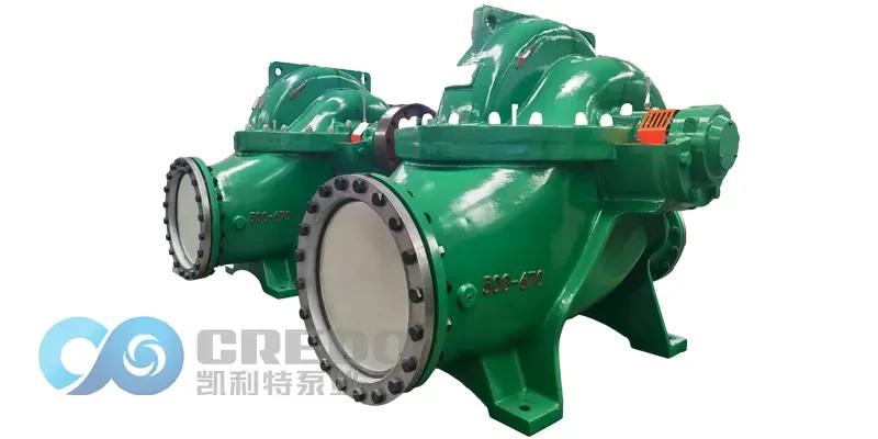
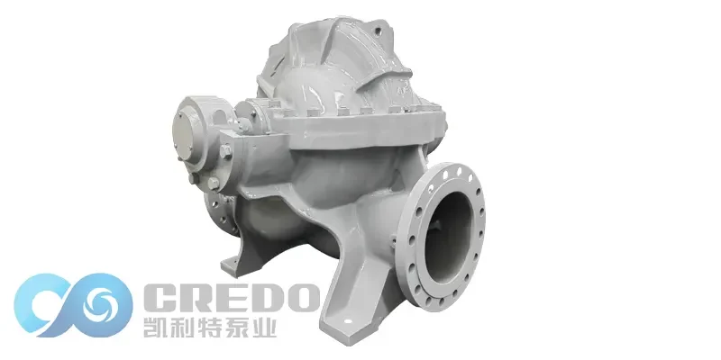
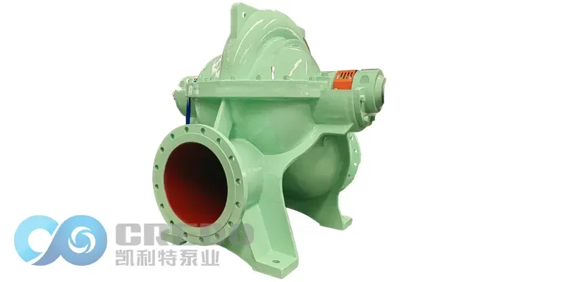
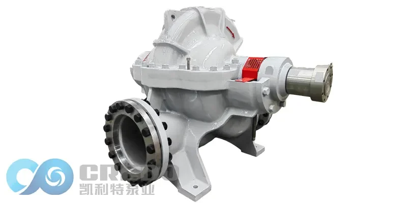
In centrifugal pump systems, the axial split case pump is widely used in municipal water supply, industrial circulation water, and large-scale cooling systems due to its high efficiency, robust structure, and suitability for large flow applications. Understanding the working point and flow regulation methods of an axial split case pump is crucial to ensure efficient and economical system operation.
Pipeline Characteristic Curve
When an axial split case pump is installed in a specific pipeline system, the pump must deliver the flow rate and head required by the pipeline. The relationship between the required head and flow rate is represented by the pipeline characteristic curve, which can usually be expressed as:
He = A + BQ²
Here, A represents the static head, which is the energy needed to overcome elevation difference, while B is the pipeline resistance coefficient, and BQ² reflects the friction losses that increase with the square of the flow rate. This formula highlights the essential nature of pipeline operation: the greater the flow, the more significant the resistance losses.
Working Point of Axial Split Case Pump
The working point of an axial split case pump is the intersection of the pump characteristic curve and the pipeline characteristic curve. At this point, the flow rate and head supplied by the pump exactly meet the system’s demand, ensuring stable operation. If the pump operates away from this point, problems such as unstable flow, increased energy consumption, cavitation, or vibration may occur. Therefore, the pump should ideally operate near its highest efficiency zone to achieve optimal energy utilization and extend service life.
Flow Regulation Methods of Axial Split Case Pump
In practical applications, operating conditions often change, and the original working point may no longer meet new requirements. In such cases, it is necessary to adjust the working point through flow regulation. Common methods include:
1. Throttle Valve Regulation
A regulating valve is installed at the pump outlet to change the slope of the pipeline characteristic curve by adjusting the valve opening.
When the valve opens wider, resistance decreases, and the working point moves toward higher flow.
When the valve closes, resistance increases, and the working point shifts toward lower flow.
Advantages:Simple to operate and flexible in adjustment.
Disadvantages:A partially closed valve increases energy loss, making it difficult for the pump to operate at its best efficiency point. This method is more suitable for small-range, frequent flow adjustments rather than large-scale regulation.
2. Speed Regulation
By changing the motor speed, the entire pump characteristic curve can be altered, causing proportional changes in flow rate and head. This method maintains high efficiency within a certain range and is more energy-efficient. However, it typically requires variable frequency drives or special control systems, making it relatively costly.
3. Impeller Diameter Trimming
Reducing the impeller outer diameter can change the pump characteristic curve, adapting the pump to new working conditions. This method is effective for long-term, fixed operating conditions and helps maintain high efficiency. However, it is not suitable for frequent changes and has a limited adjustment range.
Conclusion
In summary, the working point of an axial split case pump is determined by the intersection of the pump and pipeline characteristic curves, directly affecting the efficiency and stability of the system. Regarding flow regulation, throttle valve control is practical for small and frequent adjustments, speed regulation is more energy-saving but requires higher investment, and impeller trimming is suitable for long-term fixed conditions. Choosing the right regulation method ensures stable operation, reduces energy consumption, and extends the service life of the axial split case pump.